


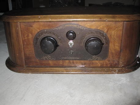
The instruction card inside the radio indicates the radio is an Arborphone AC 37. This is a totally different radio than the Arborphone 37 AC. This radio has the same cabinet as the more common Model 27. As the name implies the radio is made to run on AC. I have not spent much time with this radio but it has an AC power cord. There is a transformer that supplies the filiament power for the tubes and an auxillary AC power outlet that is meant to power and optional B eliminator. The B voltages could also be supplied via batteries if desired.
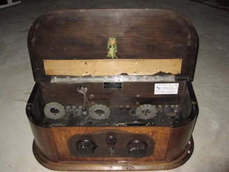
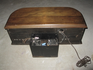
Here are a few more photos. This radio has some documentation with it that says it was restored in 1978. One obvious "improvement" is a B eliminator has been bolted to the rear of the radio. Also the volume control and power switch have been replaced. The outside of the cabinet has been re-finished in ureathane. I intend to remove these improvements in the future and restore it at least to it's original appearance.
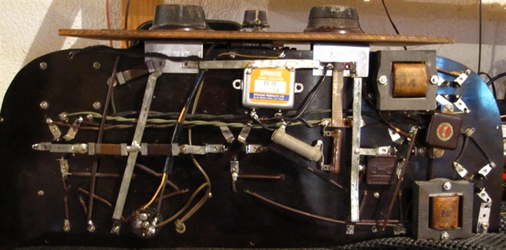
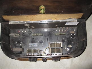
Above is a photo of the underside. There is a couple of high wattage resistors someone added to make up for an original resistor that is open. The large 1 uF capacitor also does not appear to be original.
I was able to make this radio play using a 112A as the final output tube. My ARBE III supplied the detector 45 volts and the 135 volts for the rest of the tubes. I used a variac to power the internal filament supply. Adjusting the variac such that the 112A filament was 5 volts resulted in the other tubes to have a somewhat reduced filament voltages. The radio received a local station with reasonable volume.
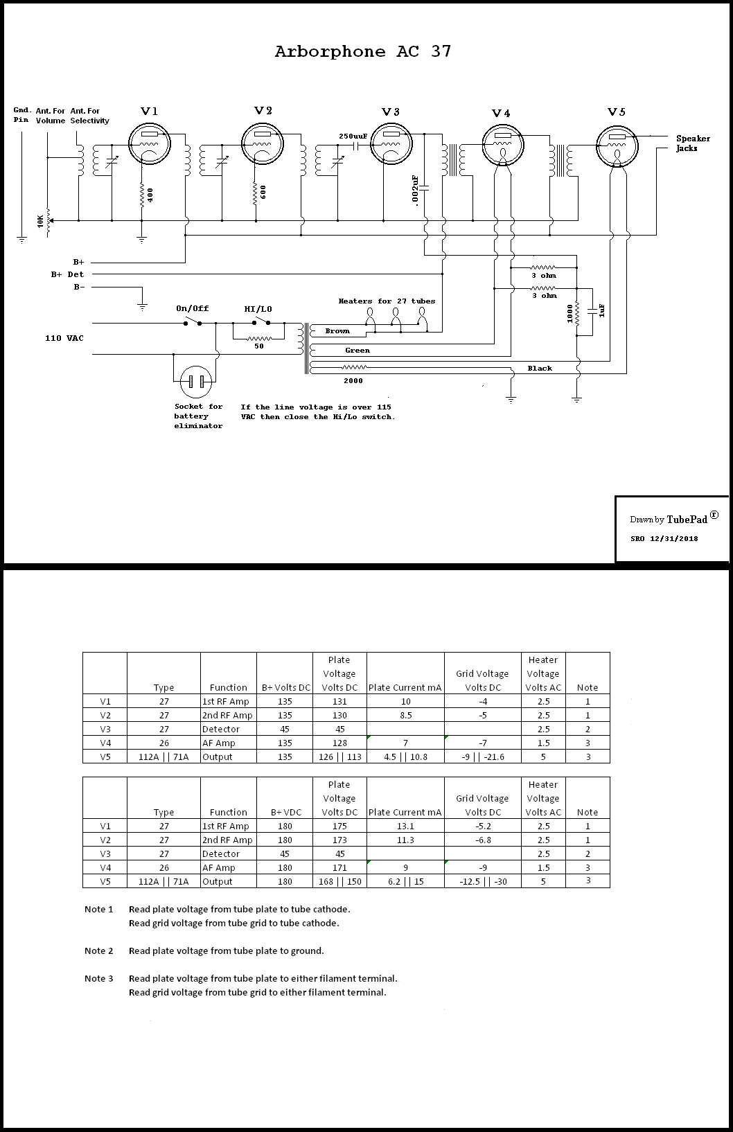
Intersting thing to note is that the filament winding for the output tube is center tapped while an "artificial center tap" is created with two 3 ohm resistors for the audio amplifier tube. The two 3 ohm resistors (measured) look like glass cartridge fuses and are located on the top of the circuit board.
I have another Arborphone AC 37 and that one is a little different. The instruction card in that radio says the final output tube to use is a 26. That suggests B voltage ranges are different as well. Using a 26 instead of a 71A as my radio uses means there probably is not a 5 volt filiament circuit in this other radio and the schematic shown above would not apply.
